Input Monitoring
IP input
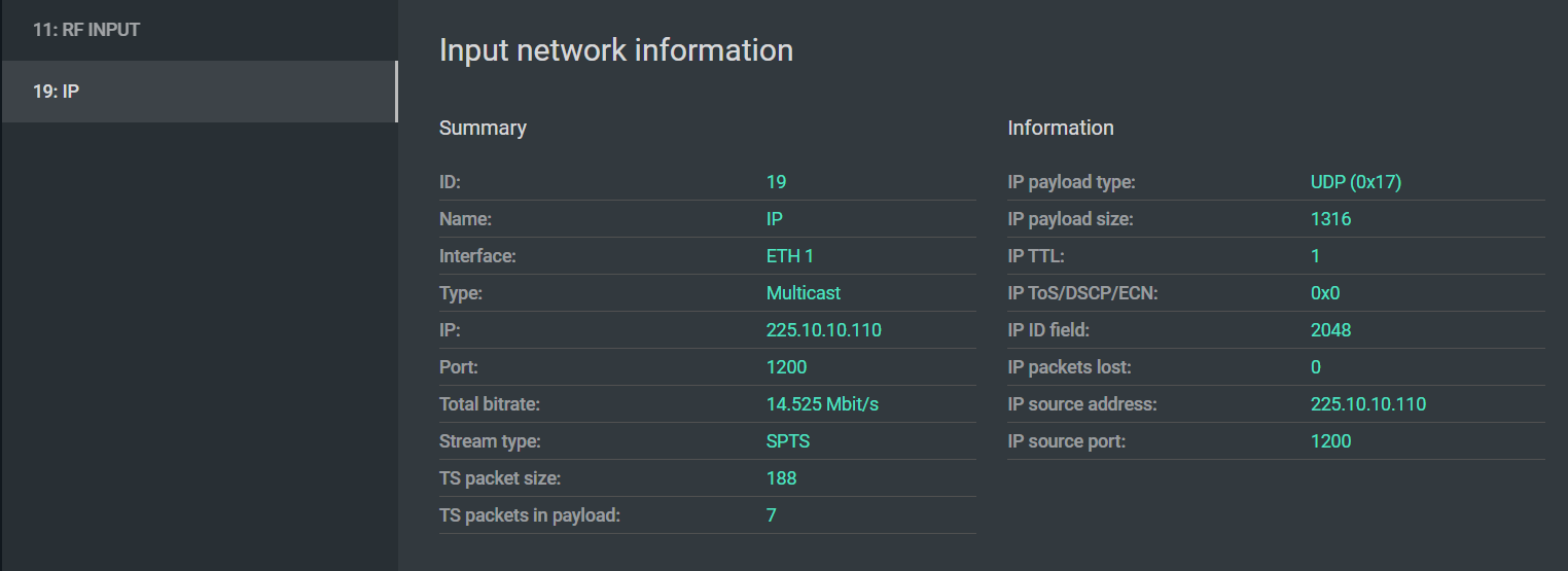
The IP input information panel provides a summary of the incoming UDP/RTP stream that is useful both for verifying correct configuration and for diagnosing transport problems.
Key fields
TS packet size — the size of TS packets encapsulated in the IP payload. The standard size is 188 bytes. Some devices use 192-byte (with timestamp prefix) or 203-byte (with Reed-Solomon) packets. Using non-standard sizes can cause compatibility problems with downstream equipment and wastes bandwidth. If you see anything other than 188 here without a deliberate reason, investigate the source.
TS packets in payload — the number of TS packets carried in each UDP packet. For a stable network, this should be as high as possible — ideally 7 — to minimize the per-packet overhead of the UDP/IP header. A value of 1 means the stream is generating far more IP packets than necessary, increasing the relative impact of network jitter and adding unnecessary load to network infrastructure.
IP TTL (Time to Live) — the number of hops remaining before the packet is discarded. For multicast streams that are expected to stay within a single LAN segment, a TTL of 1 is correct and intentional. If multicast is failing to route across network boundaries, check this value — too-low TTL is a common cause.
IP ToS / DSCP / ECN — traffic priority marking. If your network is configured to prioritize broadcast traffic, verify this field is set as expected by your network team. TS Analyzer lets you confirm whether the source device is actually setting the priority correctly.
IP payload size — should correspond to TS packet size × TS packets in payload plus the UDP header length. A mismatch can indicate a malfunctioning Ethernet interface on the source device.
Diagnosing IP stream problems
If CCE errors appear on an IP stream, start here:
- Confirm TS packets in payload — if it is 1 or very low, the stream is more vulnerable to jitter. Consider increasing the encapsulation count at the source.
- Check TTL — if the stream traverses routers, TTL must be greater than the number of hops.
- Move to the IPAT view to measure network jitter, and to MDI for DF and MLR.
RF input
The RF input panel shows a summary of the received modulated signal — frequency, standard, and basic lock status. This view is useful for confirming that the TS Analyzer is correctly configured to receive the signal.
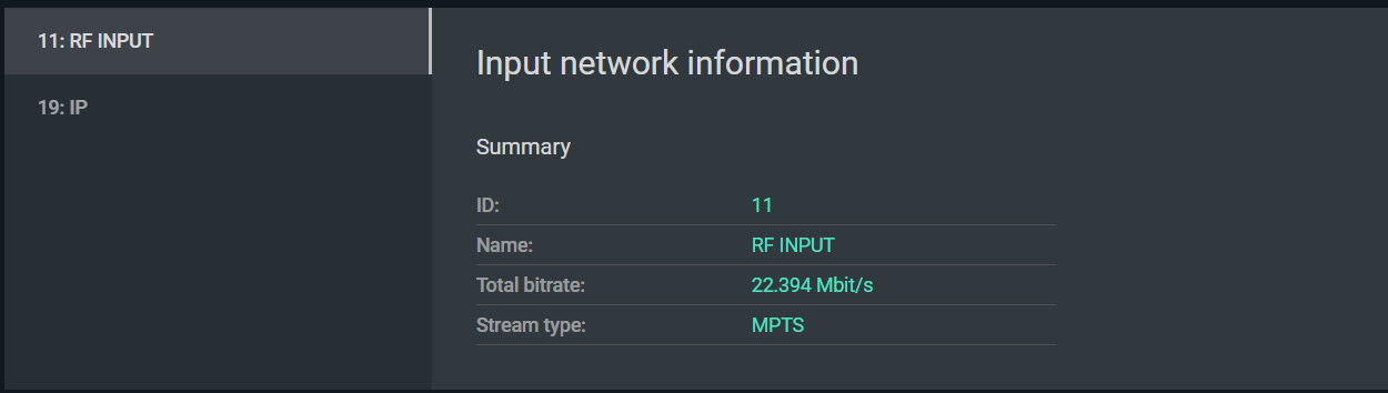
For detailed RF quality analysis — signal level, SNR, BER, and DVB-T2 modulation parameters — use the dedicated RF monitoring screen described in RF Signal Monitoring.
Verifying RF input configuration
When configuring an RF input, confirm:
- The correct center frequency is set (in MHz).
- The correct standard is selected: DVB-T, DVB-T2, or DVB-C.
- For DVB-C, the symbol rate and modulation (QAM order) match the network's parameters.
- For DVB-T2, the PLP ID is set to the correct Physical Layer Pipe if the signal carries multiple PLPs.
The input panel will indicate whether the demodulator has achieved lock. If lock is present but the transport stream shows errors, proceed to RF signal quality analysis.