RF Signal Monitoring
The RF monitoring screen displays quality indicators for the received radio signal at the TS Analyzer's RF input. These indicators reflect signal conditions at the point of measurement — the device's antenna port — and are independent of the content being transmitted.
When a problem affects an entire multiplex (all services on a single frequency), the first step is always to examine RF signal quality. A poor RF signal produces stream-level errors; fixing the stream without fixing the RF is pointless.
Primary indicators
Signal Level
Signal level measures the power of the received signal at the input. It is expressed in dBµV (decibels relative to a microvolt, used when measuring amplitude) or dBm (decibels relative to a milliwatt, used when measuring power). These are interchangeable:
L(dBµV) = L(dBm) + 108.7    (for 75-ohm systems)
L(dBm)  = L(dBµV) − 108.7
There is no single universal "correct" level — what matters is that the level is neither too low (the demodulator cannot lock) nor too high (the input stages are overloaded). Both extremes cause the same result: loss of demodulation. Practicing engineers often overlook signal overload as a cause of reception problems.
The minimum required level can be estimated as:
L_required = L_sensitivity + SNR_required
where L_sensitivity is the receiver's published sensitivity specification (typically around −80 dBm) and SNR_required is the minimum SNR for the chosen modulation. In terrestrial networks, the planned minimum level is often 68 dBµV (measured under standard antenna and feeder conditions: 12 dB antenna gain, 3 dB feeder loss, 75 Ω, 18°C).
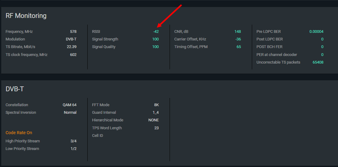
Signal-to-Noise Ratio (SNR)
SNR is the most important quality indicator for digital television — more so than signal level alone. A low SNR causes increased BER, which leads to TS_sync_loss. The required SNR depends on the modulation scheme: higher-order modulations (e.g., 256-QAM) require significantly higher SNR than lower-order ones (e.g., QPSK).
If signal level is adequate but SNR is low, interference is the likely cause. RF interference raises the noise floor without changing the signal level.
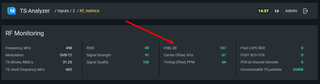
Bit Error Rate (BER)
BER is the fraction of received bits that are in error. It is closely related to SNR: worse SNR produces higher BER. BER cannot be measured quickly — it requires accumulating enough bits for statistical validity (tens of millions at minimum).
In DVB-T2, error correction is applied in two stages. TS Analyzer displays BER at each stage:
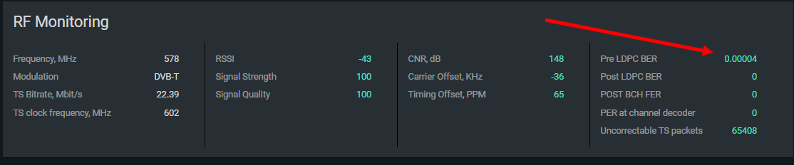
| Measurement point | Acceptable threshold |
|---|---|
| Before LDPC correction | BER < 10⁻⁴ |
| After LDPC correction | BER < 10⁻⁹ |
| After BCH correction (FER) | FER < 10⁻⁴ |
If FER is acceptable but LDPC BER is not, or vice versa, suspect a demodulator malfunction.
A high signal level combined with a high BER (many errors despite strong signal) strongly suggests interference, particularly from periodic or narrowband sources such as radar systems or spurious emissions from nearby equipment.
Secondary indicators
| Indicator | Description | When to investigate |
|---|---|---|
| Carrier offset | Frequency offset correction being applied by the AFC, in kHz | Large deviations (hundreds of kHz) prevent demodulation. Constant changes may indicate a faulty oscillator in the receiver or transmitter. |
| Timing offset | Sync signal offset in PPM relative to the local oscillator | Large deviations (thousands of PPM) prevent demodulation. Constant drift suggests oscillator problems. |
| PER at channel decoder | Ratio of erroneous TS packets to total received | PER > 10⁻⁴ will produce significant CCE counts. Reflects BER at the TS packet level. |
| Uncorrectable TS packets | Cumulative count of TS packets that could not be corrected | Steady increase indicates BER is insufficient. |
DVB-T2 modulation parameters
The DVB-T2 signal carries modulation parameters in its L1 signaling that the TS Analyzer can read and display. This information is useful for verifying modulator configuration, determining which network and transmitter is being received, and identifying the SNR requirements for the current modulation settings.
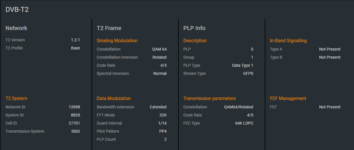
Key DVB-T2 parameters
| Parameter | Meaning | Practical use |
|---|---|---|
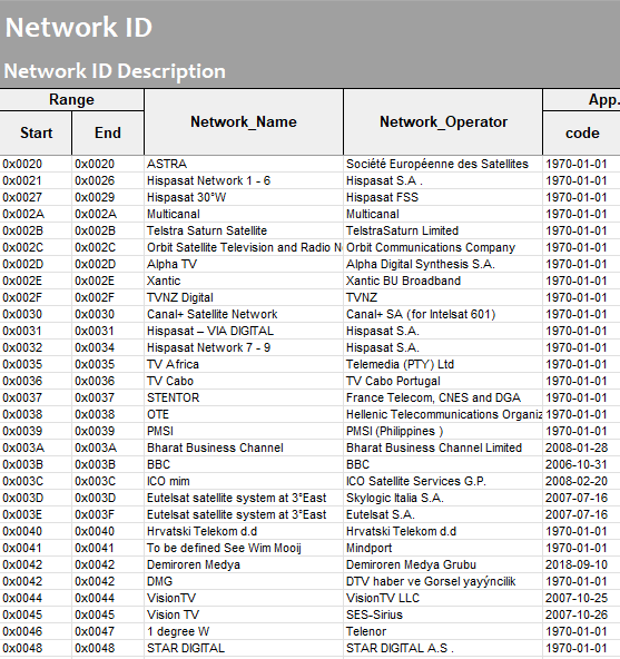
| Network ID | Operator identifier assigned by ETSI | Must match the Network ID in NIT and EIT tables. Mismatches can cause EPG failures on some devices. |
| System ID | Unique T2 network identifier within the operator's networks | Together with Network ID, identifies which network is being received. |
| Cell ID | Identifies the specific transmitter (or SFN group) | Useful for identifying which transmitter's signal is dominant at the measurement point. |
| Transmission system | SISO / MISO / MIMO | Indicates the antenna configuration in use. MIMO/MISO is rare in DVB-T2 deployments. |
| T2 Frame parameters | OFDM mode, guard interval, pilot pattern, FEC type | Compare against the expected modulator configuration. Any deviation indicates a misconfigured or malfunctioning modulator. |
| PLP Info | Parameters of the currently demodulated Physical Layer Pipe | Verify PLP configuration matches the network plan. |
Network IDs are managed by ETSI. The example below shows a fragment of the public Network ID registry: