IPAT and Duplicate Packets
IPAT (Inter-Packet Arrival Time)
IPAT measures the time between the arrival of the first bytes of two consecutive IP packets containing TS data. It is a direct measure of network jitter for IP inputs.
Jitter causes the gaps between packet arrivals to vary. The receiving device must buffer incoming packets to smooth out these variations — if the jitter exceeds what the buffer can absorb, packets arrive too late to be processed in sequence, leading to CCE errors and visible service degradation.
IPAT is also influenced by:
- Transport type — RF inputs have minimal jitter because timing is governed by the modulator's constant-rate clock. IP networks introduce variable delay.
- Stream bitrate — higher bitrates increase network load and can increase jitter.
- TS packets per IP packet — packing more TS packets into each UDP packet increases the IPAT (at constant bitrate, fewer IP packets means longer intervals), but reduces header overhead and network load.
Reading the IPAT histogram
For RF inputs, a single-bar histogram is normal and expected — IPAT is governed by the demodulator's constant clock:
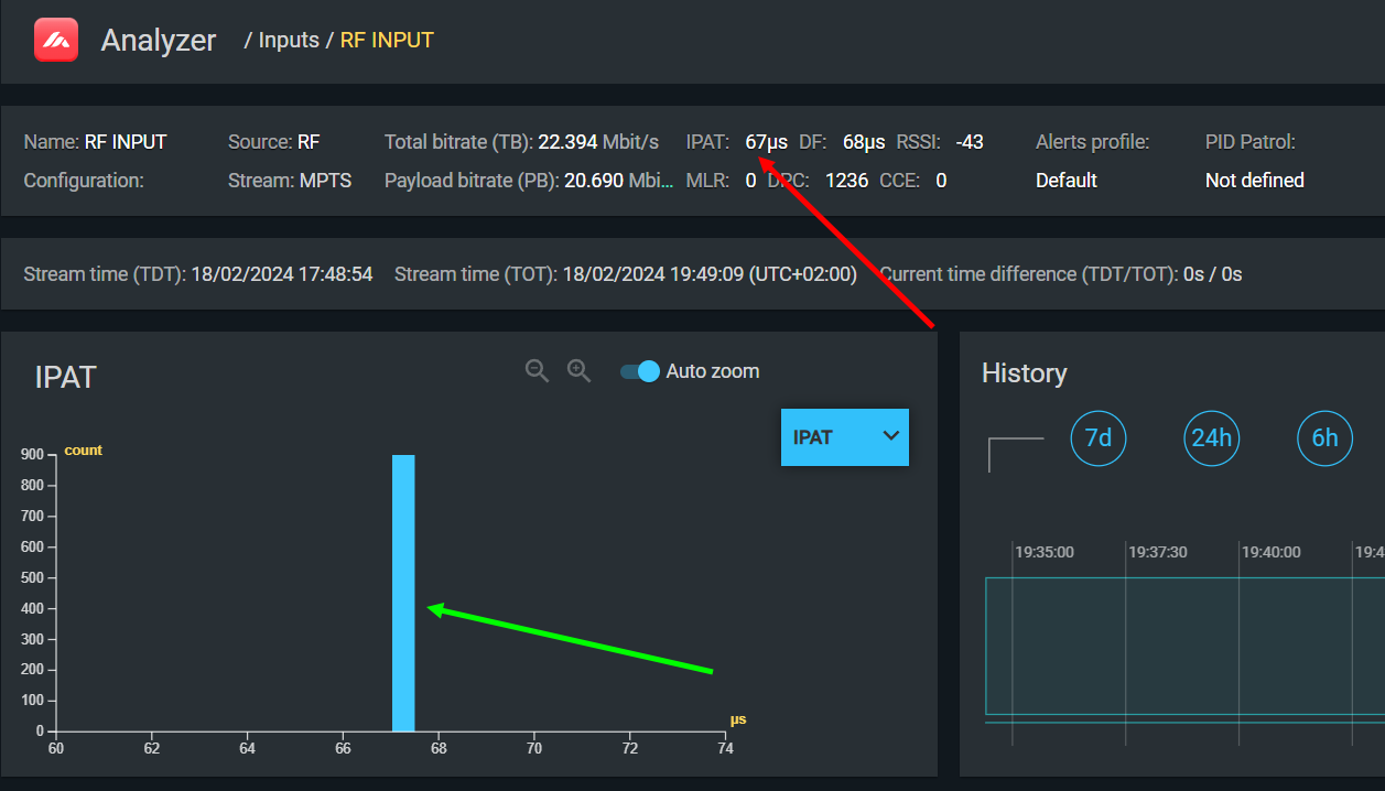
If you see multiple bars scattered across the histogram on an RF input, jitter is present in the RF path — this indicates a problem in the demodulator or its interface to the analyzer, and CCE errors are likely to follow.
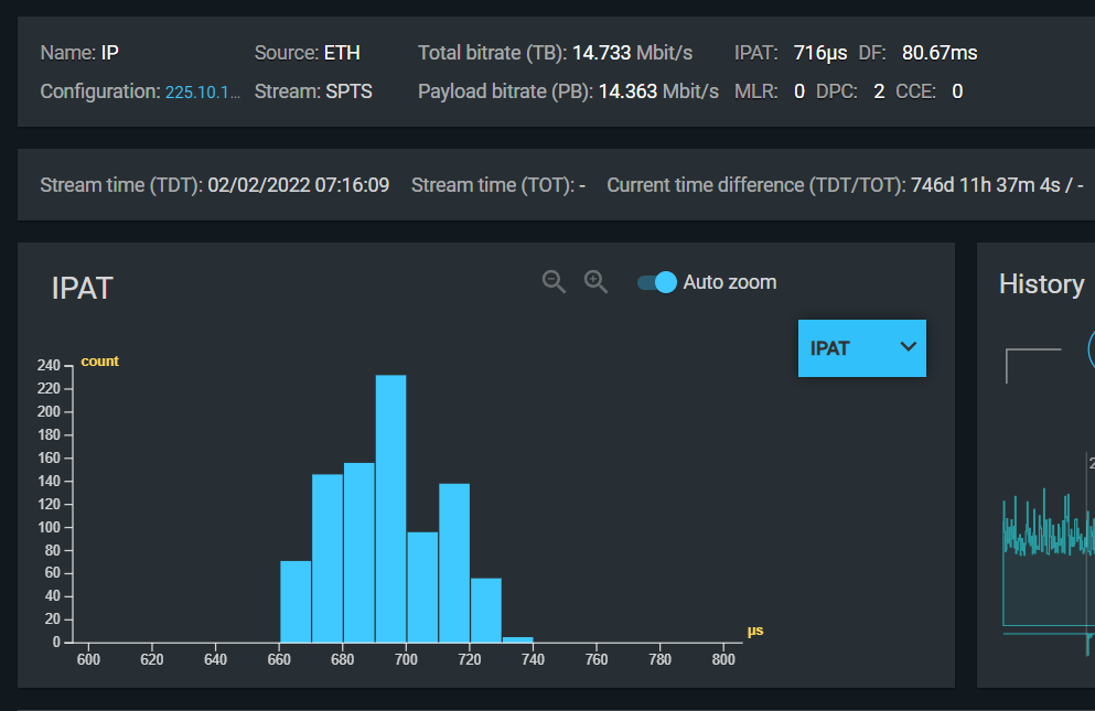
For IP inputs, a Gaussian distribution indicates a well-functioning network:
| Histogram shape | Interpretation |
|---|---|
| Single narrow bar | Essentially constant IPAT — minimal jitter. Expected for RF inputs. |
| Gaussian ("bell curve") distribution | Small random variations — healthy IP network. |
| Wide or chaotic distribution | High jitter — risk of buffer overflow/underflow and CCE errors. |
| Multiple distinct peaks | Multiple contributing sources of delay variation. |
Correlation with DF
On an RF input, the IPAT value should equal the DF (Delay Factor from MDI). If they match, the demodulator and demultiplexer are operating correctly — each packet is held in the buffer exactly until the next arrives. A discrepancy between IPAT and DF on an RF input warrants investigation.
Using IPAT to diagnose CCE
When CCE errors appear throughout a stream (on all or most PIDs) and the source appears to be IP transport rather than signal quality, check the IPAT histogram:
- A chaotic histogram confirms that network jitter is the cause.
- Measure DF to determine the minimum buffer size needed to absorb the jitter.
- If DF fluctuates synchronously with CCE, the receiver's buffer is too small for the current jitter level. Either increase the buffer size (if configurable) or reduce jitter by optimizing the network path.
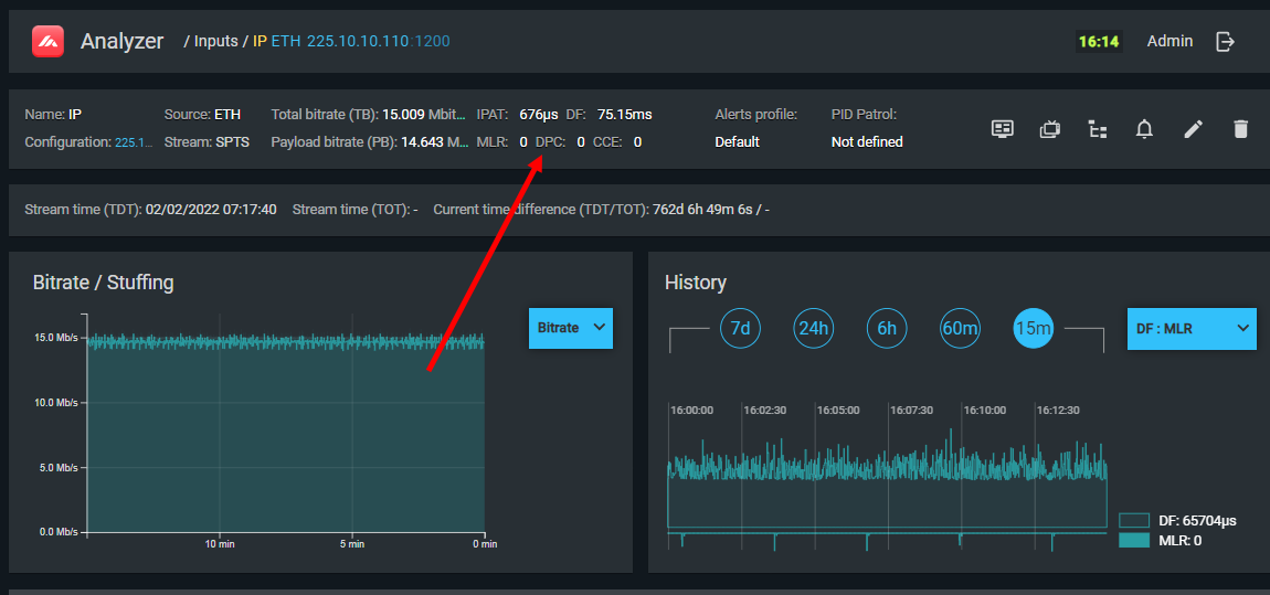
Duplicate Packet Counter (DPC)
TS Analyzer counts duplicate TS packets — packets with the same PID and continuity counter value appearing consecutively. Under normal conditions, this counter should be zero.
Duplicate packets are caused by:
- Network loops generating multiple copies of the same multicast packet
- Multiple sources transmitting to the same multicast group simultaneously
- A malfunctioning multiplexer or network switch repeating packets
Duplicates consume bandwidth without carrying new information. In large numbers, they can crowd out legitimate traffic, causing CCE errors across the entire TS as bandwidth is exhausted.
What to check
If the duplicate packet counter is non-zero and growing:
- Verify that no multicast group is being fed from more than one source.
- Check network topology for loops (spanning tree issues).
- Inspect the multiplexer generating the stream for software faults.
- Check the network switch or router between the source and the analyzer for erroneous packet duplication.